Crankshaft Position Sensor Testing: Easy Steps & Tips
Updated on June 13, 2026
Introduction
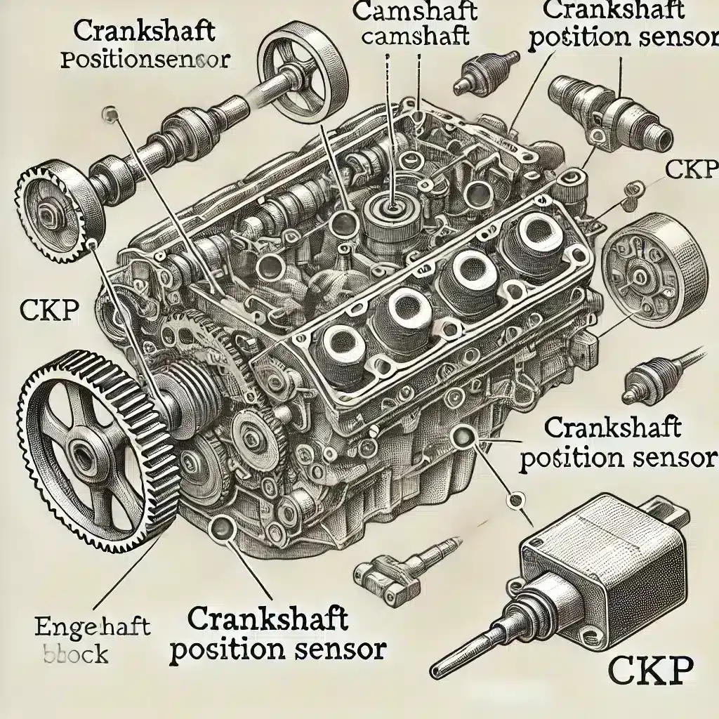
The crankshaft position sensor (CKP) is a vital component in modern internal combustion engines, providing critical data to the engine control unit (ECU) about the crankshaft’s position and rotational speed. This information is essential for precise fuel injection and ignition timing. A malfunctioning CKP sensor can lead to engine misfires, stalling, or a no-start condition. In this guide, we will delve into the intricacies of the CKP sensor, its types, symptoms of failure, and detailed testing procedures using various diagnostic tools.
Understanding the Crankshaft Position Sensor
Function and Importance
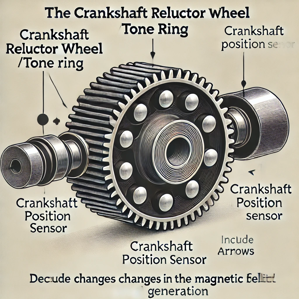
The primary role of the CKP sensor is to monitor the position and rotational speed of the crankshaft. By relaying this data to the ECU, the sensor ensures optimal timing for fuel injection and ignition, which is crucial for engine efficiency and performance. A faulty CKP sensor can disrupt this synchronization, leading to performance issues or engine failure.
Types of Crankshaft Position Sensors
Symptoms of a Faulty Crankshaft Position Sensor
Identifying a malfunctioning CKP sensor is crucial for timely maintenance. Common symptoms include:
- Engine Misfires: Inaccurate sensor data can lead to improper ignition timing, causing cylinders to misfire.
- Stalling: The engine may unexpectedly stall due to intermittent loss of sensor signal.
- Hard Starting or No-Start Condition: Without accurate crankshaft position data, the ECU may fail to start the engine.
- Illuminated Check Engine Light: The ECU detects discrepancies in sensor readings, triggering the warning light.
- Reduced Fuel Efficiency: Incorrect timing can lead to inefficient fuel combustion, decreasing mileage.
Diagnostic Trouble Codes (DTCs) Related to CKP Sensor
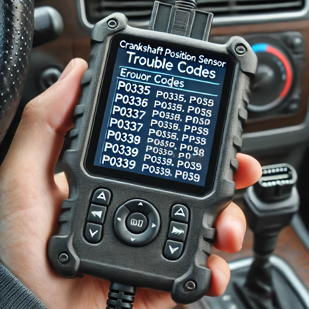
When the ECU detects issues with the CKP sensor, it stores specific DTCs, which can be retrieved using an OBD-II scanner. Common codes include:
- P0335: Crankshaft Position Sensor “A” Circuit Malfunction
- P0336: Crankshaft Position Sensor “A” Circuit Range/Performance
- P0337: Crankshaft Position Sensor “A” Circuit Low Input
- P0338: Crankshaft Position Sensor “A” Circuit High Input
- P0339: Crankshaft Position Sensor “A” Circuit Intermittent
Testing the Crankshaft Position Sensor
Accurate testing of the CKP sensor involves several methods. Below are detailed procedures for each:
1. Visual Inspection
Before delving into electrical tests, perform a thorough visual inspection:
- Connector and Wiring: Check for corroded, damaged, or loose connectors and wiring. Ensure there are no signs of wear or exposure.
- Sensor Condition: Inspect the sensor for physical damage, contamination, or debris that could affect its operation.
2. Using a Diagnostic Scan Tool
A diagnostic scan tool can retrieve stored DTCs and provide real-time data:
- Retrieve Codes: Connect the scan tool to the vehicle’s OBD-II port and check for CKP-related codes (e.g., P0335 to P0339).
- Live Data Monitoring: Observe the engine RPM readings. Inconsistent or erratic RPM signals may indicate a faulty sensor.
3. Testing with a Multimeter
Depending on the sensor type, multimeter tests vary:
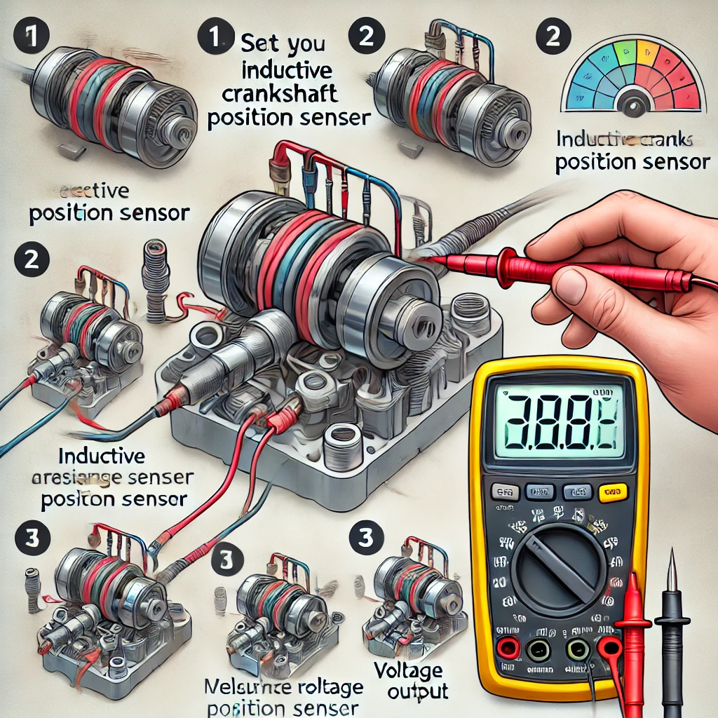
For Inductive Sensors:
- Resistance Check:
- Disconnect the sensor connector.
- Set the multimeter to the ohms (Ω) scale.
- Measure the resistance across the sensor terminals. Typical readings range between 200 to 1,000 ohms. A reading outside this range suggests a defective sensor.
- AC Voltage Test:
- Reconnect the sensor.
- Set the multimeter to AC voltage mode.
- Crank the engine and measure the voltage output. A functional sensor should produce a fluctuating voltage signal, typically between 0.5 to 1.5 volts AC during cranking.
For Hall Effect Sensors:
- Power Supply Verification:
- Turn the ignition key to the “ON” position without starting the engine.
- Set the multimeter to DC voltage mode.
- Verify the reference voltage (usually 5V) and ground at the sensor connector.
- Signal Output Test:
- Back-probe the signal wire.
- Crank the engine and observe the voltage. A properly functioning sensor will produce a pulsing DC voltage, toggling between 0V and the reference voltage.
4. Oscilloscope Testing
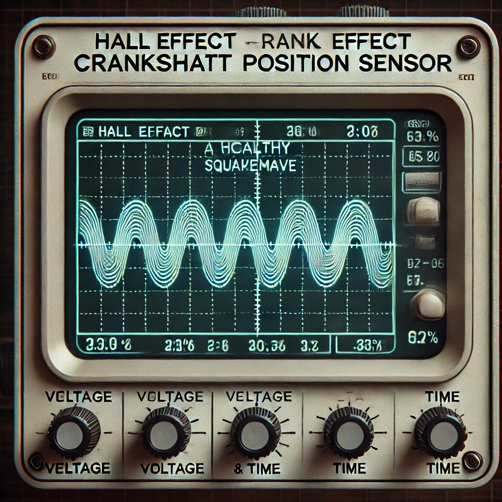
An oscilloscope provides a visual representation of the sensor’s output signal:
- Connect the Oscilloscope: Attach the probes to the sensor’s signal and ground wires.
- Capture the Waveform: Crank the engine and observe the waveform pattern. Inductive sensors produce a sine wave, while Hall Effect sensors generate a square wave. Irregularities in the waveform indicate potential issues.
Conclusion
The crankshaft position sensor is indispensable for the efficient operation of modern engines. Recognizing the signs of a failing CKP sensor and conducting thorough testing can prevent potential engine performance issues. By following the outlined diagnostic procedures, one can accurately assess the health of the CKP sensor and ensure the engine operates at its optimal performance.
Read also: Camshaft Position Sensor Replacement Guide – Step by Step
Need expert help with your setup?
Our team is ready to help you choose the right tools and get you up and running.