Camshaft Position Sensor Testing: Tools, Methods, and Common Pitfalls
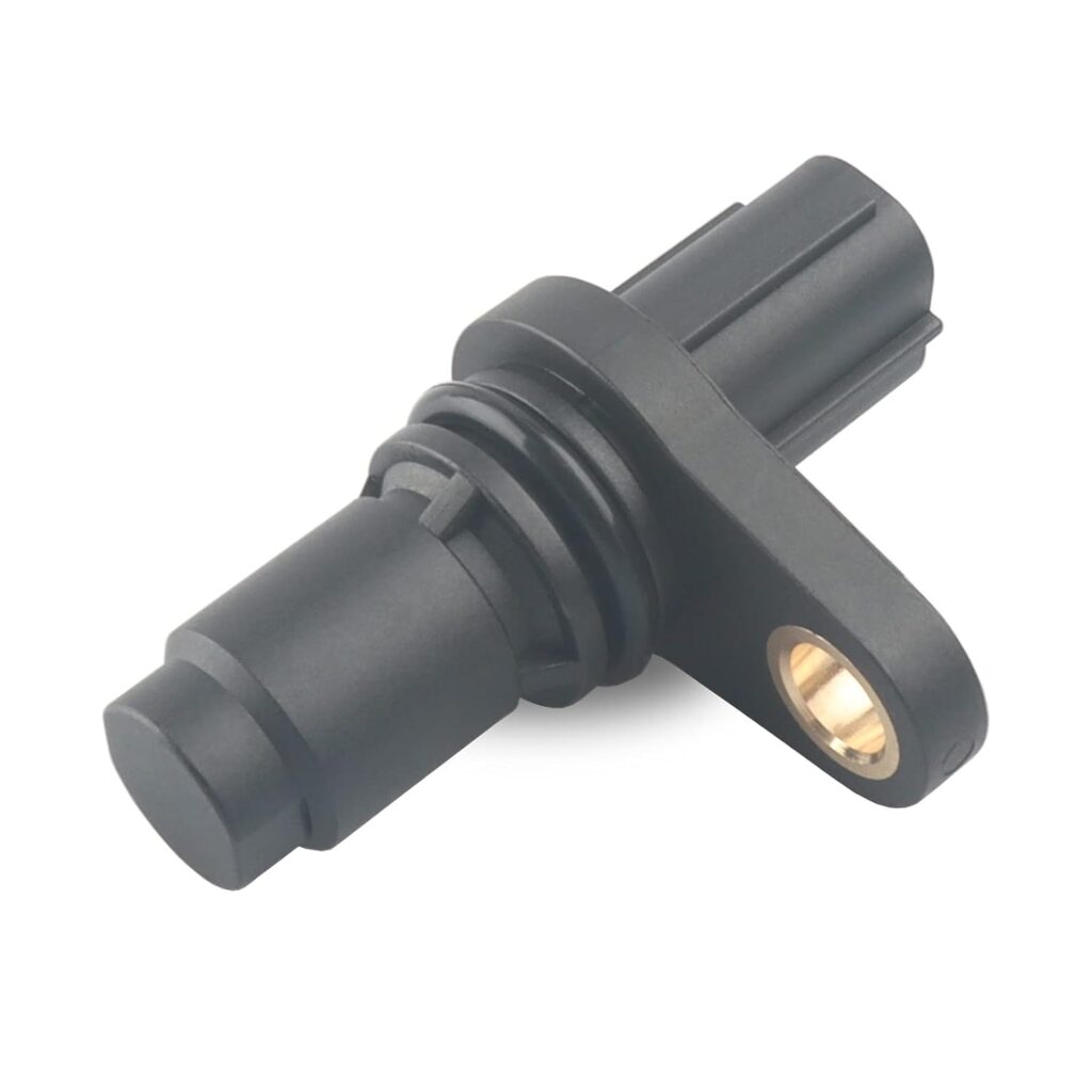
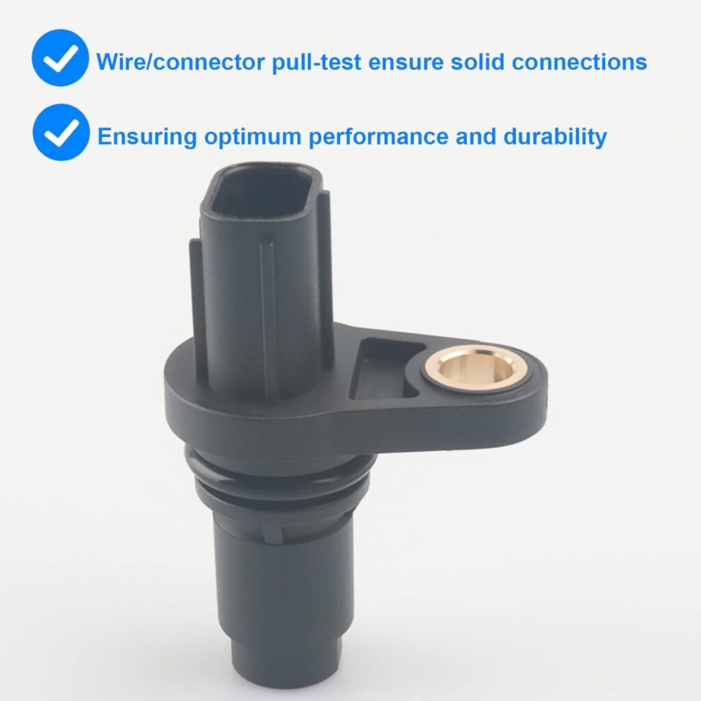
The camshaft position sensor (CMP) is a critical component in modern engines, providing essential data to the engine control unit (ECU) for precise timing of fuel injection and ignition. Accurate camshaft position sensor testing is vital for diagnosing engine performance issues and ensuring optimal vehicle operation. In this comprehensive guide, we will explore the tools, methods, and common pitfalls associated with advanced camshaft position sensor testing.

Understanding the Camshaft Position Sensor
The camshaft position sensor monitors the position and rotational speed of the camshaft, relaying this information to the ECU. This data is crucial for synchronizing the fuel injectors and ignition system, ensuring efficient engine performance and reduced emissions. There are two main types of camshaft position sensors:
- Variable Reluctance Sensors (VRS): These sensors generate an AC signal as the camshaft rotates, with the frequency and amplitude of the signal corresponding to the camshaft’s speed and position.
- Hall Effect Sensors: These sensors produce a digital signal (on/off) as the camshaft passes by a magnetic field, providing precise position data.
Essential Tools for Camshaft Position Sensor Testing
To perform advanced camshaft position sensor testing, you will need the following tools:
- Digital Multimeter (DMM): A DMM is essential for measuring voltage, resistance, and continuity in the sensor’s electrical circuit.
- Oscilloscope: An oscilloscope allows you to visualize the sensor’s signal waveform, providing detailed insights into its performance.
- Scan Tool: A scan tool can read diagnostic trouble codes (DTCs) and live data from the ECU, helping you identify issues related to the camshaft position sensor.
- Service Manual: The vehicle’s service manual provides specific testing procedures, wiring diagrams, and specifications for the camshaft position sensor.

Methods for Testing Camshaft Position Sensors
1. Visual Inspection
Before diving into electrical testing, perform a visual inspection of the camshaft position sensor and its wiring. Look for signs of damage, corrosion, or loose connections that could affect the sensor’s performance.
2. Resistance Testing
Using a digital multimeter, measure the resistance of the camshaft position sensor’s circuit. Compare the readings to the specifications provided in the service manual. A significant deviation from the specified range indicates a faulty sensor.
3. Voltage Testing
With the engine off, use the digital multimeter to check the sensor’s voltage supply. Ensure the sensor is receiving the correct voltage as specified in the service manual. Next, with the engine running, measure the output voltage of the sensor. For Hall Effect sensors, you should see a digital signal (on/off), while VRS sensors will produce an AC voltage signal.
4. Signal Waveform Analysis
An oscilloscope is invaluable for analyzing the camshaft position sensor’s signal waveform. Connect the oscilloscope probes to the sensor’s signal wire and ground. Start the engine and observe the waveform on the oscilloscope screen. A healthy sensor will produce a consistent and clean waveform. Any irregularities, such as missing or distorted signals, indicate a problem with the sensor or its circuit.
5. Scan Tool Diagnostics
Use a scan tool to read any stored DTCs related to the camshaft position sensor. Additionally, monitor the live data stream to observe the sensor’s performance in real-time. Look for any anomalies or inconsistencies in the sensor’s data.

Common Pitfalls in Camshaft Position Sensor Testing
1. Ignoring the Basics
One of the most common pitfalls is overlooking basic checks, such as visual inspections and ensuring proper electrical connections. Always start with these fundamental steps before proceeding to more advanced testing.
2. Misinterpreting Oscilloscope Waveforms
Interpreting oscilloscope waveforms requires experience and knowledge. Misreading the waveform can lead to incorrect diagnoses. Familiarize yourself with the expected waveform patterns for different types of camshaft position sensors.
3. Overlooking Intermittent Issues
Intermittent issues can be challenging to diagnose, as they may not be present during testing. Pay attention to any symptoms reported by the vehicle owner and consider performing tests under various operating conditions to capture intermittent faults.
4. Neglecting Related Components
A faulty camshaft position sensor can affect other engine components and vice versa. Ensure you check related components, such as the crankshaft position sensor, wiring harness, and ECU, to rule out any interconnected issues.
Conclusion
Advanced camshaft position sensor testing is a critical skill for automotive technicians and enthusiasts. By understanding the tools, methods, and common pitfalls associated with this process, you can accurately diagnose and resolve issues related to the camshaft position sensor. Regular maintenance and thorough testing ensure optimal engine performance, reduced emissions, and enhanced vehicle reliability.
By integrating these insights and best practices into your diagnostic routine, you’ll be well-equipped to master camshaft position sensor testing and maintain the health of your vehicle’s engine.
Read also:


